Rolling gates & Cantilever Gates FAQ
There are always questions by first time buyers about the difference between a Rolling Gate and a Cantilever Gate. The description below explains it clearly.
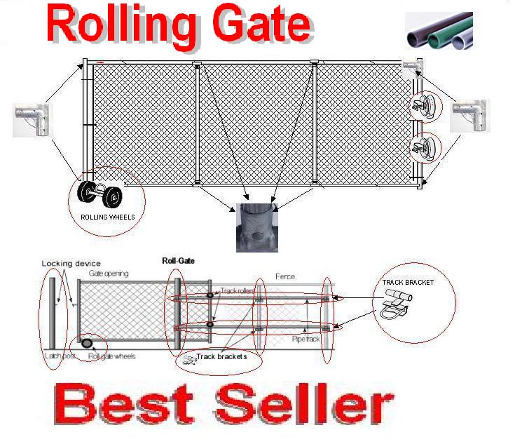
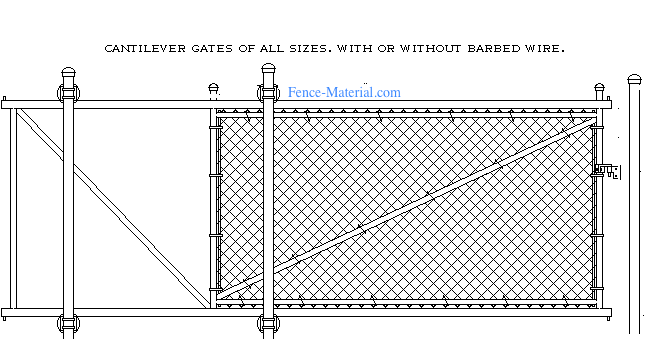
A Rolling gate rests and rolls on the ground wheel carrier. It is always the size of the opening of gate; whereas a Cantilever slide gate ( Figure 2) is 50% longer than the opening so it is held above ground (about 6"), as it slides and in closed position the extra length (counter balance) is held between the cantilever rollers which are mounted on the posts, 2 above and 2 below. Figure 1 below shows rolling gate has 2 track wheels that are mounted to the back vertical of the gate frame, assembled with a wheel bracket. The wheels roll back and forth on the pipe tracks (shown 2 horizontal pipe rails in the middle of posts). The track wheels each also have a safety clamp that overlaps over the track rails and holds the gate upright and prevents it from falling forward. This is very popular solution for residential, light commercial and interior commercial / industrial uses where the space limitations do not allow for swing gates or cantilever gates.
ROLLING GATE FIGURE 1

GENERAL ROLLING GATE INSTALLATION GUIDELINES
A rolling gate is the most efficient solution for gate applications where swing gates are not practical. However, it requires level grade to allow the carrier wheels to roll along the opening smoothly. To install a rolling gate:
1. Assemble the gate frame as shown in the diagram. Layout the gate at the opening and mark the gate-post and latch post locations, and the track line posts based on the size of your gate purchased. The spacing of the track line posts are on the opening side measured exactly to receive the tracks without any seams between track bracket.
2. Install the larger posts on either side of your opening, and track line posts at marked locations in concrete, making sure they are plumb vertical 90 degrees to the surface until it fully cured. Make sure the top of the concrete around the posts pitches away from the post to direct water away from the post.
3. Attach universal track brackets one foot from the bottom of the fence and one foot down from the top of the fence. The brackets are installed so that the U-bolt is below the track sleeve. You will need to install all brackets to support all track lengths of track as provided to allow your gate to open in full opening position. Measure from bracket to bracket. install 1 5/8” tracks between the brackets. Be sure that your track is tight between the brackets so that you do not create a seam for the wheels to get caught-up. Once complete you should have a top and bottom track that is consistently the same distance apart from one end to the other. This is important to prevent the track from binding on the rear track wheels.
4. Install rear track wheels on the rear vertical support of the gate. The wheels will be approximately one foot from the top and bottom of the gate. The wheels will be installed on the outside face of the gate so as to ride on top of the track. Hand-tighten.
5. Install the double wheel carrier as far forward towards the latching post direction as you can on the bottom horizontal member of the gate.
6. Placing the gate in the opening with both rear track wheels on top of the track, adjust the rear track wheels so that both wheels bear down on the track. Make sure the lower guide on the wheels captures the track so that you can not lift the gate off the track but the guide does not bind while traveling the track. Tighten the wheels.
7. Roll the gate through the opening. Adjust the rear track wheels as necessary. The double wheel assembly has an axle trim bolt that allows you to control the direction of the gate as it rolls through the opening. Adjust as necessary.
8. Using two end bands that fit around the latch post, install the offset lock n’ latch so that when the gate comes fully closed the tab on the latch is engaged, capturing the gate frame and allowing you to padlock the latch.
9. You may have to adjust the double wheel assembly back on the frame so that the gate will engage the latch.
10. Firmly secure all nut & bolt connections to avoid future movement.
CANTILEVER GATE FIGURE 2

The Cantilever gate shown in figure 2 has two gate roller posts and one latch post. The gate slides between the two rollers on top and bottom and is also held up by these rollers. As it slides to close, the counterbalance which is the extra length of the gate, is held between the two rollers. Cantilever gates require enough space for full length of the opening plus the counter balance on the opening side. These gates are always welded and the horizontal rails on top and bottom are always 2.375 inch OD. All different size rollers are made for this size of horizontal the rails. The size of the roller varies by the size of the post these are being mounted on, for example 3" OD, 4"OD or 6 5/8" OD.
